Measuring RC Circuit Current with an Arduino
Published 2021/09/26
Using the analog pins of an Arduino it is possible to measure the voltage across a resistor. With a known value of resistor this can be used to deduce the current flowing in a circuit* using ohm's law
$$\begin{align}\Delta V = IR\end{align}$$
With the ability of an Arduino to quickly and accurately sample the voltages analysis can be performed that far outstrips the ability of a human with a multimeter. To highlight this the following experiment was conducted in order to verify the equation describing the current in an Resistor and Capacitor (RC) circuit
$$\begin{align}I(t) = \frac{\varepsilon}{R}e^{-\frac{t}{RC}}\end{align}$$
Where $I(t)$ is the current as a function of time, $\varepsilon$ the voltage provided to the circuit, $R$ the resistance of the resistor in the circuit, and $C$ the capacitance of the capacitor. A general rule of thumb for RC circuits is that the capacitor will charge in 5 time units $\tau$ where
$$\begin{align}\tau = RC\end{align}$$
Given a capacitor of size $100\times 10^{-6} F$ and a resistor $220 \Omega$, the capacitor will reach capacity in roughly $0.11 s$. An almost unobservable amount of time for a human, however these were the components selected for the analysis.
The circuit and arduino was set up per Figure 1 with analog pins A0 and A1 connected either side of the resistor, and +5V and GND pins used to power the circuit.
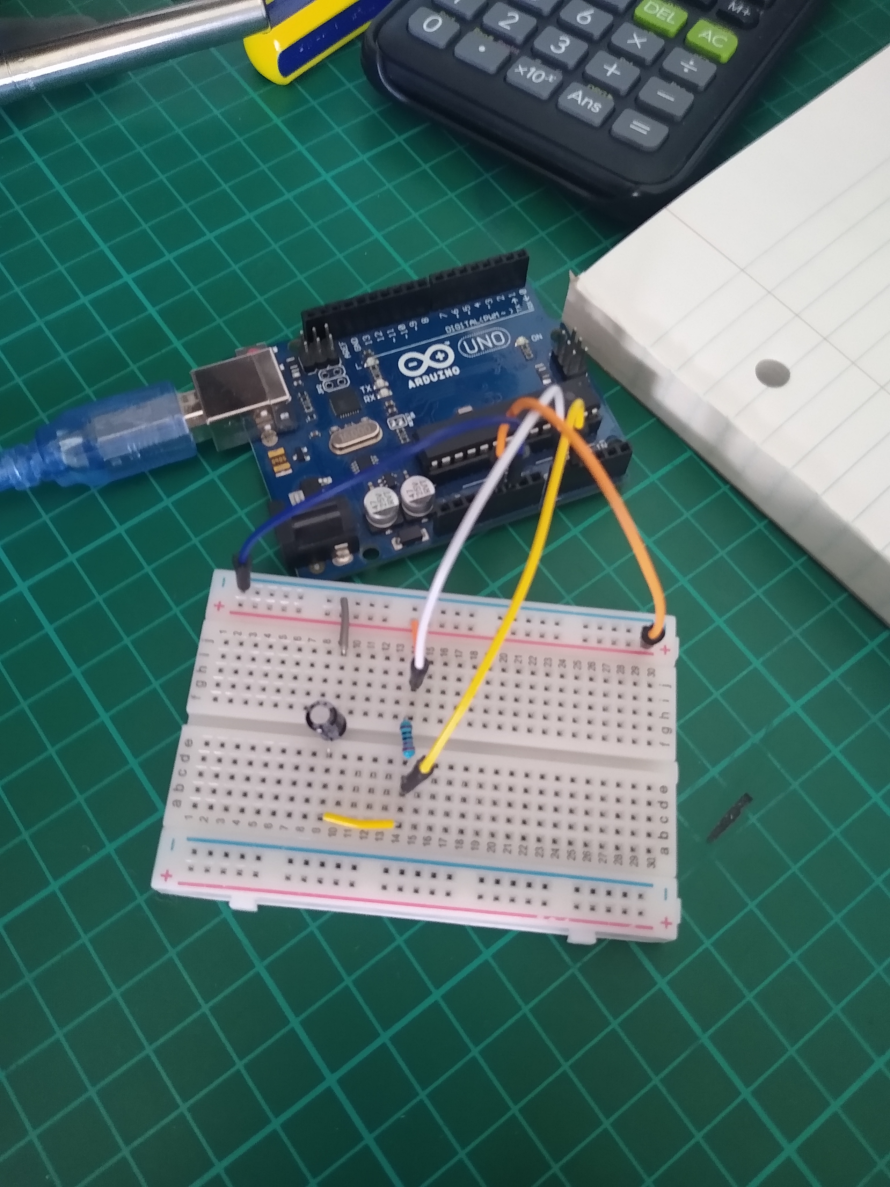 |
| Figure 1 - Arduino setup with analog pins connected to either side of the resistor. Note the arduino was also used to supply 5V to the circuit. |
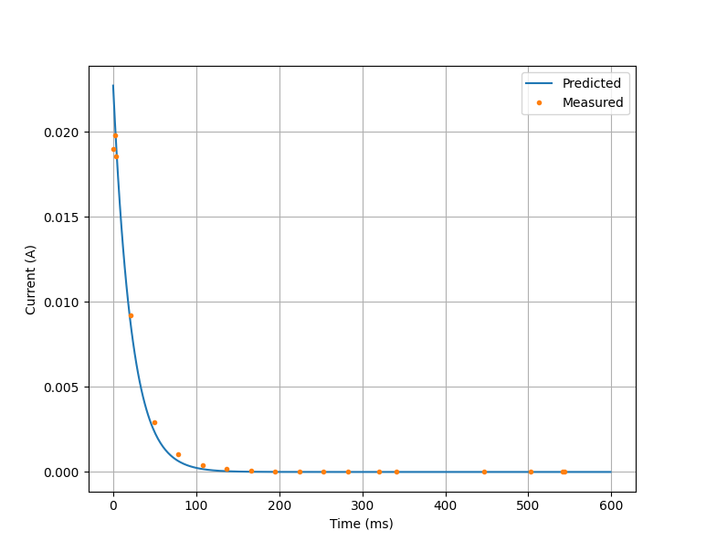 |
| Figure 2 - Graph with predicted and measured current of the circuit. The predicted model was made with Equation 2. |
Surpsingly the data found and the model match up near perfectly, with the current dropping to near zero in roughly $100-150 ms$, as the rule of thumb predicted. The apparent lag behind the model could be due unideal component behaviour or inaccuracy in the data.
UPDATE (19/10/2021):
Code used to analyse data from Arduino is now avaliable on my Github.
*With >5V and a common ground.